10 Print Interpretation
Print Interpretation
This final section introduces basic print reading. Because machine drawings are used to some extent in nearly every trade, the working drawings used in this section are all machine drawings.
The purpose of this package is to provide an opportunity to put your fundamental knowledge of print reading to use before you go on to more specialized and advanced print reading activities.
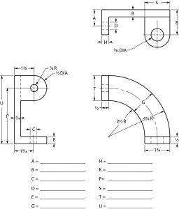
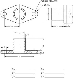
Exercise 1
Study the print below and fill in the related dimensions.
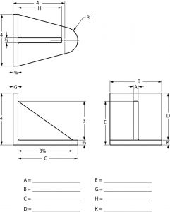
Exercise 2
Study the print below and fill in the related dimensions.
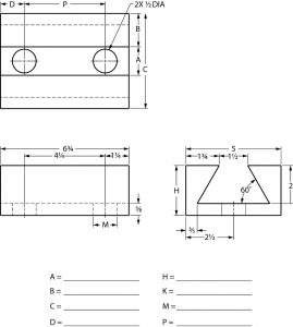
Exercise 3
Study the print below and fill in the related dimensions.
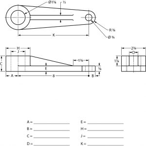
Exercise 4
Study the print below and fill in the related dimensions.
Exercise 5
Study the print below and fill in the related dimensions.