9 Machined Features

Machined Features

  • BEVEL
  • BOSS
  • CHAMFER
  • COUNTERBORE
  • COUNTERSINK
  • DOVETAIL
  • FILLET
  • KERF
  • KEYWAY
  • KEYSEAT
  • KNURL
  • LUG
  • NECK
  • PAD
  • ROUND
  • SPLINE
  • SPOTFACE
  • T-SLOT

The machined features in this section are common terms related to basic industry processes. These terms are often found on prints. For a better understanding of these processes, look at the models of machined features in the Print Reading Lab.
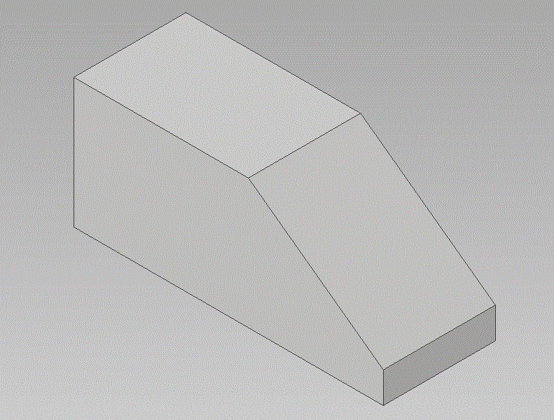
Bevel

A surface cut at an angle. In regard to welding, a bevel will normally end up being a surface prep for a weld.


Block with a 45 degree but for welding called a bevel.    The image portrays a three-dimensional geometric object set against a gradient gray background. The object appears to be a truncated rectangular prism with one side sloping downwards, forming a trapezoidal face. It is white with black outline lines defining its shape. The top face is a rectangle, and the front face is a smaller rectangle due to the sloping cut of the right side. The overall structure resembles a wedge.

Boss

A circular pad on forgings or castings, which project out from that body of the part. The surface of the boss is machined smooth for a bold head to seat on and it has a hole drilled through to accommodate the bolt shank.
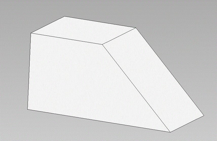
Piece of metal with a raised surface for welding called a boss.    The image depicts a 3D rendering of a rectangular block with a cylindrical feature on its surface. The block is oriented diagonally, showcasing a three-dimensional perspective. The central feature is a circular indentation, with a smaller circle inside it. The surface and the sides of the block display a smooth texture and are uniformly colored in shades of white and gray to indicate depth and shadow. The overall composition is minimalistic, focusing on the geometric shapes.

Chamfer

A process of cutting away a sharp external corner or edge. Not for welding.
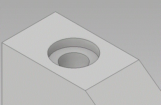
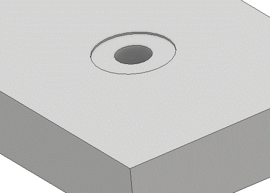
Block cut at an angle to remove the sharp edge.    The image displays a three-dimensional geometric shape resembling a truncated wedge. The shape has a rectangular base with two parallel surfaces connected by slanted sides that converge towards a smaller top surface. The structure is depicted against a light gray gradient background, providing contrast against the white or light gray color of the shape. The lines outlining the shape are thin and precise, giving it a crisp and defined appearance.

Counterbore

To enlarge drilled hole to a given diameter and depth. Usually done for recessing a bolt head.
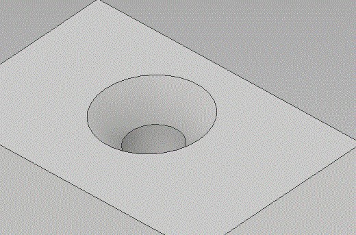
Block of material showing an example of a counterbore.    The image is a computer-generated 3D rendering of a geometric object. It features a rectangular solid with a smooth, light gray surface. The top face of the object has a circular recess, which appears as a concentric ring creating a cylindrical cavity. This cavity is slightly beveled around the edge, adding depth and dimension. The exterior faces of the object display a uniform texture, enhancing its symmetrical appearance.

Countersink

To machine a conical depression in a drilled hole for recessing flathead screws or bolts.
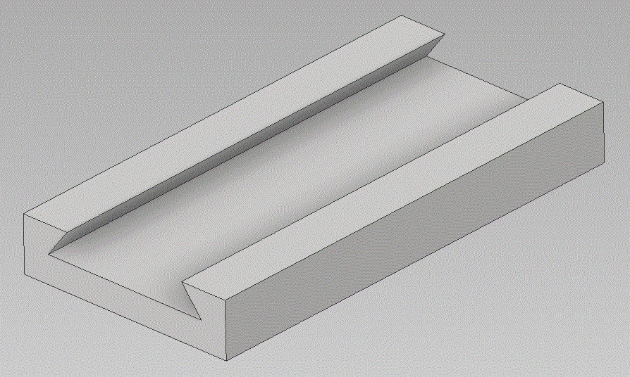
Part with a countersink hole to accommodate a tapered screw.    The image depicts a 3D rendering of a rectangular block with a circular, conical hole in the center. The block is oriented with its longer sides horizontal, and the hole appears to taper inward, creating a funnel-like shape. The surface of the block and the interior of the hole are smooth, with shading used to emphasize depth and dimension. The block and hole are shown in a grayscale color scheme, highlighting the geometric simplicity and clean lines of the design.

Dovetail

A slot of any depth and width, which has angled sides.
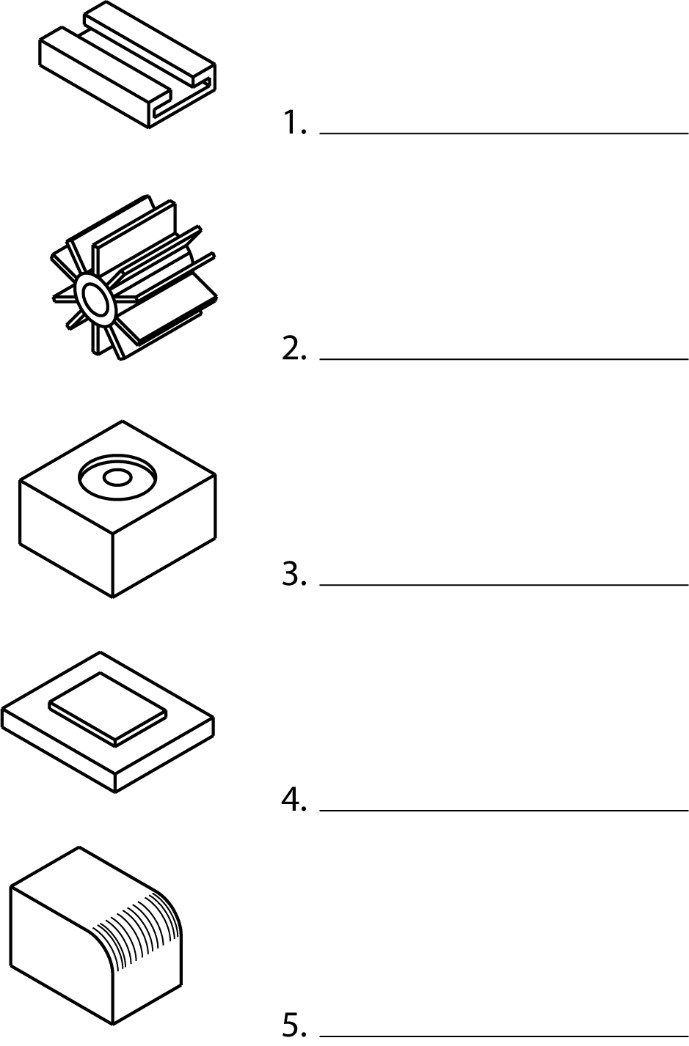
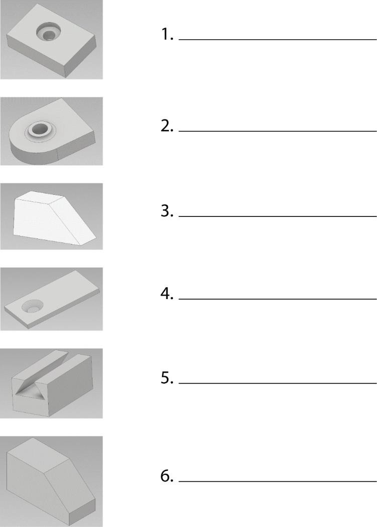
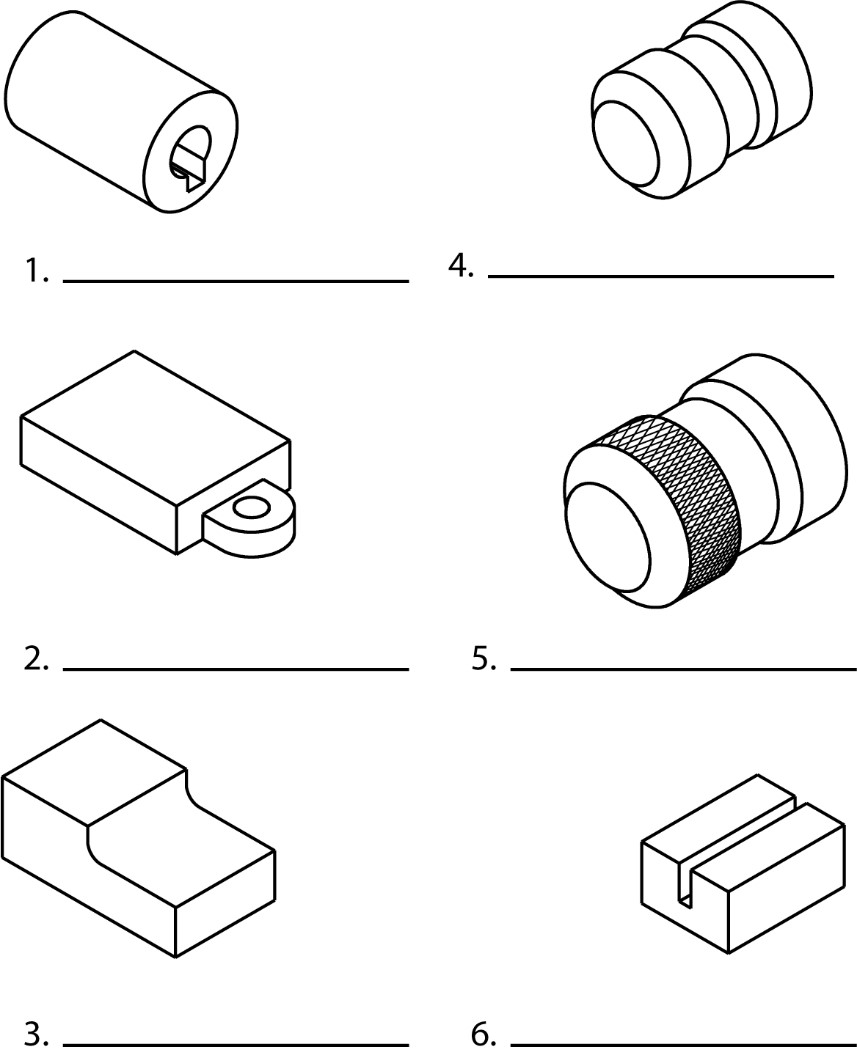
Image showing a dovetail cut in a piece of material.    The image depicts a three-dimensional rendering of a simple geometric structure resembling a rectangular channel or groove. The structure consists of a solid block with a prominent groove cut into its center, running parallel along its length. The groove has a V-shaped cross-section, with slanted sides converging at the bottom. The object is light gray and positioned against a neutral gray background, allowing the edges and angles of the structure to be clearly visible. The lighting creates subtle shadows within the groove, highlighting its depth and shape.


Quiz

Directions: Name the machined features shown below.

graphic quiz for identification of surfaces and holes.    The image is a vertical arrangement of six 3D geometric shapes on the left side, numbered 1 to 6, with lines for labeling on the right.    Starting from the top, Shape 1 is a triangular prism with a circular hole through the top surface.  Shape 2 resembles a quarter circle prism with a flat top and circular indentation.   Shape 3 is a slanted rectangular prism with angled surfaces.   Shape 4 is a long rectangular prism with a circular hole through one end.   Shape 5 features a block with a V-shaped groove on the top.   Shape 6 is a complex form with combined rectangular and slanted elements.

Fillet

A small radius filling formed between the inside angle of two surfaces.
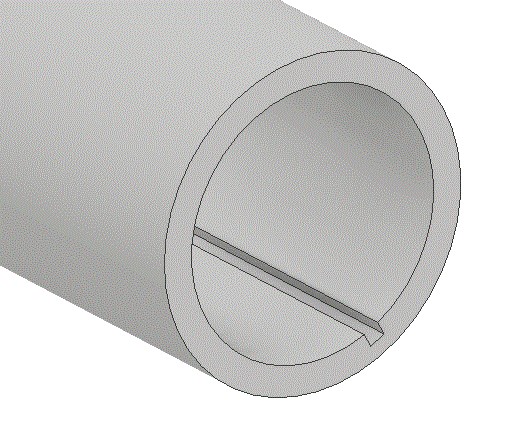
Material showing a fillet.    3D block with a step and curved notch.    The image depicts a three-dimensional geometric object, resembling a block with a right-angled step and a curved notch. The block has a rectangular base and a smaller rectangular section elevated at one end, creating a step. The transition between these two levels features a smooth, concave curve. The object has a uniform gray color and is shown on a white background, giving a clear view of its shape and dimensions.

Kerf

The narrow slot formed by removing material while sawing or other machining.

Material showing a kerf    The image depicts a simple gray 3D geometric shape resembling a block with a rectangular cutout. The block has a rectangular, solid form with two main sections separated by a gap. The gap runs parallel to the longer side of the block, creating two parallel, elevated rectangular prisms on either side. The perspective shows a slightly angled view from above, highlighting the depth and length of the cut.

Keyway

A narrow groove or slot cut in the shaft hole of a sleeve or hub for accommodating a key.

Keyseat

A narrow groove or slot cut in a shaft for accommodating a key.
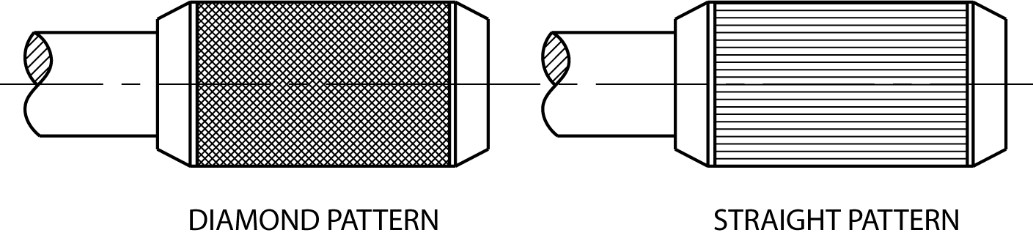
Image showing a keyseat.    The image shows a 3D rendering of a cylindrical pipe with a grey, matte texture. The pipe is oriented horizontally, extending from the left side of the image. There is a rectangular slot running longitudinally inside the pipe, visible at the open end on the right. The inner part shows a consistent thickness around the circumference.

Knurl

To uniformly roughen with a diamond or straight pattern a cylindrical or flat surface.
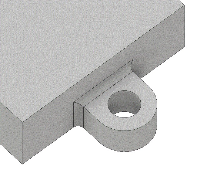
 

Example of different knurl types.    Two cylindrical objects with diamond and straight patterns.    The image features two side-by-side illustrations of cylindrical objects, each with different surface patterns. The object on the left displays a diamond pattern, characterized by a grid of crisscrossing diagonal lines, creating a textured appearance. The object on the right features a straight pattern, with parallel horizontal lines running across its surface. Both cylinders have a pipe extending out from one end. Each pattern is labeled below the respective object.

Lug

A piece projecting out from the body of a part. Usually rectangular in cross section with a hole or slot in it.
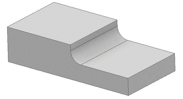
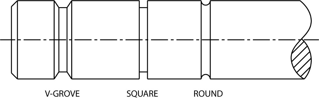
Showing a lug welded onto a piece of material for purpose of attachment.    The image shows a close-up view of a mechanical component with a simple geometric design. The component is primarily a rectangular block extending outward. At one corner of the rectangle, there is a protruding cylindrical shape with a hole in the center. This cylindrical part appears to be a mounting feature or attachment point. The component is uniformly colored in a light gray with a smooth surface texture.

Neck

To machine a narrow groove on a cylindrical part or object.

Shows cuts made on a lathe into a piece of round stock.    The image is a black and white technical drawing of a cylindrical object with three distinct sections. The first section on the left features a V-groove, characterized by a beveled edge, creating an angular notch. The middle section is square-shaped, with flat surfaces and straight edges. The section on the right shows a rounded end with a circular profile. The circular end is partially shaded with diagonal lines, indicating a cutaway or cross-section. A dashed centerline runs horizontally through the entire drawing, suggesting symmetry and alignment of the sections. Below each section, corresponding labels are provided: "V-GROVE" under the first, "SQUARE" under the second, and "ROUND" under the third.

Quiz

Directions: Name the machined features shown below. Check your answer.

Visual quiz to identify the surfaces discussed.    The image displays six line-drawn isometric shapes arranged in two rows.    In the top row, the first shape is a cylindrical object with a hollow and a protruding feature inside.   The second shape is a rectangular solid with a small circular tab extending from one face.   The third shape is an irregular block with a stepped design.   The fourth shape resembles a cylindrical object with multiple grooves.  The fifth shape is similar to the fourth but has a textured band around its center.   he sixth shape is a rectangular block with a central, vertical slit.

Additional features and shapes.
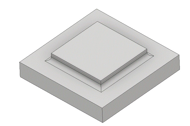
Pad

A slightly raised surface projecting out from the body of a part. The pad surface can be of any size or shape. (Remember, bosses can only be round)
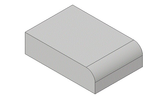
Shows a pad welded onto a part.    The image depicts a three-dimensional rendering of a geometric structure composed of two stacked square platforms. The larger, lower platform is a square with thick edges, appearing slightly skewed due to the perspective. On top of the larger square, there is a smaller square platform, centered and raised, creating a step-like formation. The structure is colored in shades of gray, giving it a uniform, monochromatic appearance.

Round

A small radius rounded outside corner formed between two surfaces.
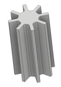
Show the rounding off of a sharp edge.    The image shows a three-dimensional, gray rectangular prism with a smooth, curved edge along one of the shorter sides. The prism has a flat top surface and the sides are vertical and straight, except for one side where the corner is rounded, giving it a more aerodynamic shape.

Spline

A gear-like serrated surface on a shaft. Take the place of a key when more torque strength is required.
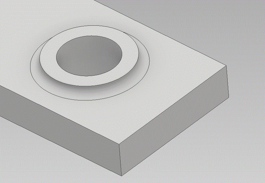
A gear shape.    3D rendering of a gray, gear-like cylindrical object with a star-shaped top and six extensions.    The image displays a 3D rendering of a gray, gear-like object positioned vertically. The object has a cylindrical form with a star-shaped top, featuring six evenly spaced, protruding rectangular extensions. These extensions create a gear-like appearance, with deep grooves running along the length of the structure between each extension. The surface appears smooth, and the overall geometry is symmetrical.

Spotface

A round surface on a casting or forging for a bold head. Usually about 1/16” deep.
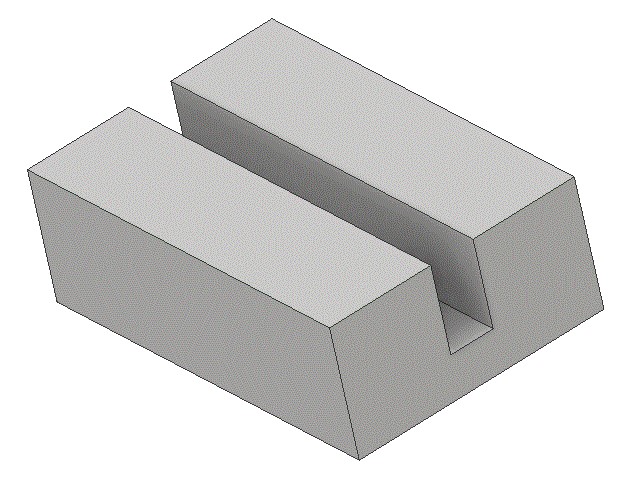
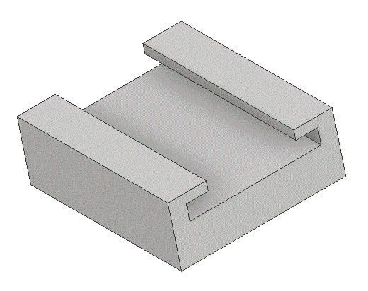
A round surface on a casting or forging for a bold head.    The image depicts a three-dimensional rendering of a grey rectangular block with a circular hole in the top surface. The block is oriented with its longer edges running horizontally, and the circular hole is positioned centrally in the upper surface. The edges and sides of the block are defined with clear lines, providing a sense of depth and perspective.

T-Slot

A slot of any dimensions to resemble a “T”.

A slot of any dimensions to resemble a “T”.    The image depicts a 3D gray object with a rectangular base and two parallel sides extending upward. The structure resembles an open box with three sides, where the two longer sides are positioned opposite each other. The top of the object features narrow protruding ledges extending inward from each vertical side, creating a stepped appearance.

Quiz

Directions: Name that machined features shown below. Check your Answers.

Quiz identifying the surfaces discussed.    The image features five distinct 3D mechanical components, each numbered sequentially from 1 to 5, with lines beside them for labeling.     The first component is a rectangular channel with a U-shaped cross-section.   The second component resembles a gear with radial fins extending outward.   The third component is a cuboid with a circular indentation on the top surface.   The fourth component is a flat, square piece with a raised, smaller square in the center.   The fifth component is a rounded rectangular block with a series of parallel grooves on one side.


License

Icon for the Creative Commons Attribution-NonCommercial-ShareAlike 4.0 International License

Blueprint Reading For CAD I Copyright © by SBCCOE is licensed under a Creative Commons Attribution-NonCommercial-ShareAlike 4.0 International License, except where otherwise noted.

Share This Book