2 The Language of Lines


  • OBJECTLINE
  • HIDDEN LINE
  • SECTION LINE
  • CENTER LINE
  • DIMENSION LINE
  • EXTENSION LINE
  • LEADER LINE
  • CUTTING PLANE LINE
  • BREAK LINES
  • PHANTOM LINES
  • BORDER LINE

You have heard the saying, “A picture is worth a thousand words”. This statement is particularly true in regards to technical drawings.

It would be almost impossible for an engineer, designer, or architect to describe in words the shape, size, and relationship of a complex object. Therefore, drawings have become the universal language used by engineers, designers, technicians, as well as craftsmen, to communicate the Information necessary to build, assemble and service the products of industry.

It is Important to remember, as you study Print Reading, that you are learning to communicate with the graphic language used by Industry: Lines are part of that language.

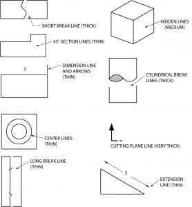
Since technical drawings are made of lines, it is logical that the first step in learning to “read” a drawing is to learn the meaning of each kind of line. Generally, there are 11 basic types of lines. Each kind of line has a definite form and “weight”. Weight refers to line thickness or width. When combined in a drawing, lines provide part of the Information needed to understand the print.

Being able to interpret a blueprint and accurately build objects is a needed skill to become successful in all trade crafts.  It is a skill, like many others you will learn, and it will take time and practice to fully understand and become proficient.
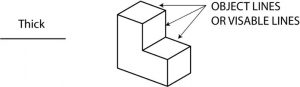
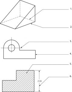


Object Line


A visible line, or object line is a thick continuous line, used to outline the visible edges or contours of an object.
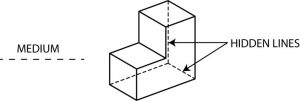
Solid object showing the use of thick lines consisting of the following:    A diagram showing a stepped cuboid with bold lines labeled as "OBJECT LINES OR VISIBLE LINES." To the left, a thick line labeled "Thick."


Hidden Line

A hidden line, also known as a hidden object line is a medium weight line, made of short dashes about 1/8” long with 1/16”gaps, to show edges, surfaces and corners which cannot be seen. Sometimes they are used to make a drawing easier to understand. Often they are omitted in an isometric view.
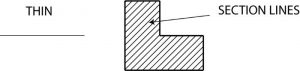
L shaped solid showing the use of hidden lines which are not solid  The image shows a line drawing of a geometric shape composed of two interlocking rectangular prisms. The drawing includes solid lines for visible edges and dashed lines to represent hidden edges. Arrows point to the hidden lines, labeled with the text "HIDDEN LINES." To the left, a dashed line is labeled "MEDIUM," indicating a different style or type of line.


Section Line

Section lines are used to show the cut surfaces of an object in section views. They are fine, dark lines. Various types of section lines may indicate the type of material cut by the cutting plane line.
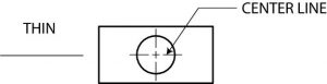
The image presents a simple technical illustration featuring a rectangle with a notched section, filled with diagonal section lines.     It is a solid block sliced in half with, showing thin lines at a 45 degree angle.     The illustration is divided into two parts. On the left, a single thin horizontal line is labeled "THIN." On the right, a notched rectangle is filled with parallel diagonal section lines slanting from the upper right to the lower left. A labeled arrow points to these lines with the text "SECTION LINES," indicating the pattern


Center Line

Center lines are used to indicate the centers of holes, arcs, and symmetrical objects. They are very thin (size), long-short-long kinds of lines.
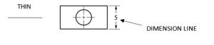
Rectangle with circle in middle indicating the use of a thin center line type.    The image displays a simple line drawing composed of a rectangle with a circle inside it, centered horizontally. The circle contains a cross at its center indicating a center line. Two lines extend diagonally from opposite sides of the circle toward the words "CENTER LINE" located at the top right outside the rectangle. To the left, outside the rectangle, the word "THIN" is written with a horizontal line extending next to it.


Dimension Line

Dimension lines are thin and are used to show the actual size of an object. There are arrowheads at both end that terminate at the extension lines.
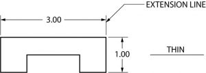
 

Rectangle showing a dimensioning line type.    The image features a technical drawing diagram. On the left side is a horizontal thin line labeled "THIN." To its right, there is a rectangle with a small circle inside it, which is centrally aligned. The circle is marked with crosshairs indicating its center. To the right of the rectangle, an arrow points to a vertical line labeled "5," which is indicated as a dimension line. The arrow is also labeled "DIMENSION LINE."


Extension Line

Extension lines are also thin lines, showing the limits of dimensions. Dimension line arrowheads touch extension lines.
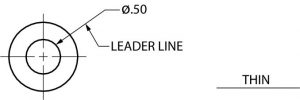
A "C" shaped rectangular object showing the use of dimensioning.    The image is a technical drawing of a geometric shape resembling a bracket. It displays a rectangular profile with a cut-out section at the bottom center. The upper rectangle has dimensions labeled as 3.00 units wide, while the depth from the top to the cut-out section is labeled as 1.00 unit. To the top right, there is a label indicating an "EXTENSION LINE" pointing to one of the thin lines extending from the shape. Another label on the right reads "THIN," aligning horizontally with the bottom edge of the bracket, indicating the thickness of the lines.

Leader Line

Leaders are more thin lines used to point to an area of a drawing requiring a note for explanation. They are preferably drawn at a 45° angles.
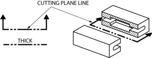
Round object with a dimension line at a 45 degree angle indicating the diameter.    The image shows a technical drawing featuring a circular shape with a smaller concentric circle inside, both intersected by crosshairs. The circles are labeled with a dimension of "Ø0.50" indicating the diameter of the smaller circle. A leader line is shown pointing to these circles. To the right, the word "THIN" is depicted above a thin horizontal line.


Cutting Plane Line

A cutting plane line (very heavy) helps to show the internal shape at a part or assembly by slicing through the object.

A rectangular block sliced in half to show internal features using the cutting plane line to indicate where it is cut and what the view is as a result.    The image is a technical illustration showing a cutting plane in a mechanical or architectural context. On the right side, there's an isometric view of a rectangular 3D object with a horizontal cut through it, revealing its interior section. This section shows semicircular grooves running through the length of the object. Above the section, the exterior remains intact, depicted with solid lines. On the left, there is a diagram of a 'U'-shaped thick line with arrows on both ends, labeled as "CUTTING PLANE LINE," indicating the sectioning location. Below this, the word “THICK” is marked with a broken line pattern to denote line style.

Break Line

There are three kinds of break lines used in drawings. They are used to remove, or ‘break out” part of a drawing for clarity, and also to shorten objects which have the same shape throughout their length and may be too long to place on the drawing.

Break lines usage to show a shortened part for better documentation of rectangular or cylindrical objects.    The image displays three separate diagrams, each illustrating a different type of break line in mechanical drawings. In the top left corner, there is a rectangular shape with a wavy line cutting through its center labeled "SHORT BREAK (THICK)." This indicates a thick, wavy line suggesting a short break in material. The top right diagram shows a thinner rectangular shape with a zigzag line through the center, labeled "LONG BREAK (THIN)." This represents a thin line with a long break. At the bottom, there is a rectangular shape with a semicircular pattern on one side, labeled "CYLINDRICAL BREAK (THICK)," illustrating a thick, cylindrical break. Arrows point to each type of break with corresponding labels.

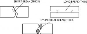
Short and long break lines are used for flat surfaces. Cylindrical are used on rods, dowels, etc.
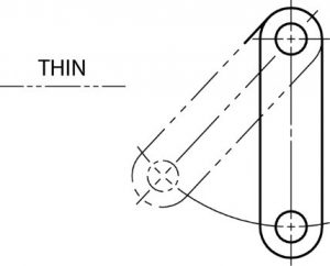
 

Phantom Line

Phantom lines are long-short-short-long lines most often used to show the travel or movement of an object or a part in alternate positions. It can also be used to show adjacent objects or features.
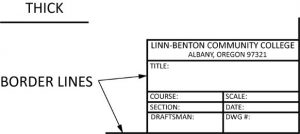
Rectangular object shown in start and finished rotated positions.    The image is a technical drawing illustrating a mechanical linkage. It features two circles connected by two parallel lines, resembling a belt and pulley system. One circle is positioned at the top right and the other at the bottom left. Both circles have a + symbol at their centers, indicating rotational axes. Phantom (dashed or long -short- short- long) lines extend from each circle, representing the path of movement or mechanical connections. The term "THIN" is inscribed to the left of the drawing with a horizontal line (dashed or long-short- short long) extending from it.

Border Line

Borderlines are very thick, continuous lines used to show the boundary of the drawing or to separate different objects drawn on one sheet. They are also used to separate the title block form the rest of the drawing.
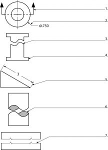
Shows use of border lines that are used to outline drawing title box.    The image depicts a section of a technical drawing, specifically focusing on the title block area. In the top-left corner, the word "THICK" is written next to a horizontal line, indicating the thickness of the border lines. Below, an arrow labeled "BORDER LINES" points to a rectangular title block on the right side. The title block contains multiple fields, each outlined, for inputting information; these include fields for the community college's name and address at the top, followed by spaces for the title, course, section, draftsman, scale, date, and drawing number.

Quiz….

Directions: Name the types of lines shown below. Check your own answers

3 geometric shapes using the lines discussed in this chapter.    The image features three different drawings, each associated with labeled lines pointing to specific parts.    The top drawing is an isometric rendering of a geometric shape with a slanted top surface and visible dashed lines indicating hidden edges.     The second drawing is a side view of an L-shaped object with a circular hole, featuring reference lines extending from the center.     The third drawing is a cross-section of a stepped object with a hatched pattern indicating a solid material and a vertical dimension line marked with 2.00 at the bottom step.     The numbers 1 to 6 are used to label specific parts in each drawing, with lines extending from these numbers to the related areas of the objects.


A print example used in industry.    The image is a detailed technical drawing for a structural column, labeled "ONE - COLUMN - 1009C." The drawing is divided into several sections and views, including details and cross-sections, providing precise measurements and specifications. The left side features a large vertical section view of the column, annotated with numerous dimensions, angles, and codes. It includes designations such as "p1236" and "W6x30." The right side displays various cross-section views labeled with letters, from "SECT. A" to "SECT. H," showing different parts of the column structure in detail. Each section includes specific measurements, bolt positions, and material notes. A "BILL OF MATERIAL" table on the top right lists parts, quantities, descriptions, lengths, and weights. The bottom right corner includes project information for "Las Positas College-Academic Bldg 100." A logo for "SUNSTEEL" is also present. Several notes mention instructions like "OPEN HOLES ARE FOR HIGH STRENGTH STRUCTURAL BOLTS."

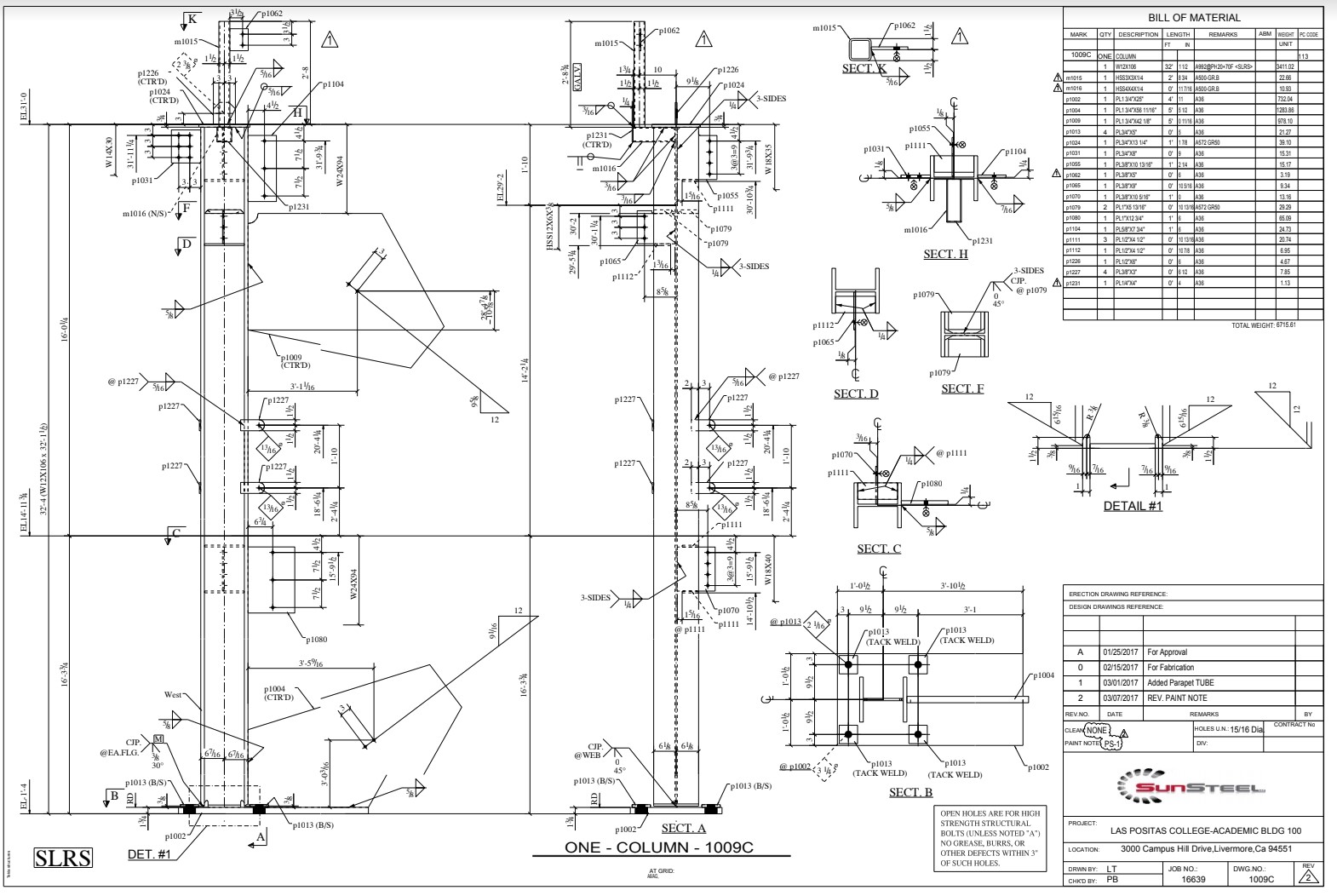
Identify the various line types used in this drawing. (instructor will provide a copy of this drawing)


Name the types of lines shown below. Check your own answers.

The image depicts a series of technical drawings, each labeled with a number. At the top is a circular representation with two opposing arrows pointing outward, labeled with the number 1. Below it, a diameter measurement marked as 0.750. Following down is an I-beam shape marked with number 3, showing a wavy pattern in the middle section. Another labeled line leads to a triangular wedge-shaped object with a slanted top edge, marked as 5. This is followed by a rectangular shape with a central, horizontal wavy line cutting through it, labeled 6. Lastly, there are two rectangular shapes at the bottom, each labeled with a 7. The lines connecting these parts are thin and straight, suggesting different sections or profiles.


 Directions: Draw and identify the lines needed to complete the figures as indicated.

Various geometric shapes asking the student to draw the missing line.    The image presents a technical drawing with various line styles used in engineering and architectural plans. In the top-left corner, there is a short, thick break line connected to a diagram labeled "3" with arrows. Below it is a thin, straight dimension line with arrows. Adjacent to it is a cube with medium hidden lines. Towards the center right, there is a cylindrical break line, illustrated with a thick, wavy curve. Further down, a circle with intersecting thin center lines is shown. Beneath it, a diagram illustrating a long, thin break line is positioned vertically. At the bottom-right, a cutting plane line is very thick and shows an arrow pointing upwards. Next to it, a triangle marked "3" has thin extension lines extending from its corners. Each line style is annotated with a brief description and indication of its thickness.


License

Icon for the Creative Commons Attribution-NonCommercial-ShareAlike 4.0 International License

Blueprint Reading For CAD I Copyright © by SBCCOE is licensed under a Creative Commons Attribution-NonCommercial-ShareAlike 4.0 International License, except where otherwise noted.

Share This Book