4 Technical Sketching

Technical Sketching

  • SKETCHING TECHNIQUES
  • LETTERING
  • OBLIQUE SKETCHING
  • ISOMETRIC SKETCHING
  • ORTHOGRAPHIC SKETCHING
  • ON-THE-SPOT SKETCHING

On many occasions in your work it will most likely be necessary for you to make a sketch. Perhaps your boss can’t visualize a particular problem without one, or you find it’s necessary to make a dimensioned sketch to show an apprentice how to complete a job. In any case knowing how to sketch can make you more effective, and therefore more valuable, as a tradesperson.

Many times out in the field you are working on sketches drawn on anything from napkins, cardboard, wood scrapes or any flat surface. Don’t get me wrong, you will work projects with professionally produced drawings but sometimes you have to work with what you have.

Being able to make technical sketches doesn’t mean you need to be an artist; and sketching isn’t difficult if you follow a few simple rules. You may be a little slow at first, but with some practice you will be able to turn out reasonably good sketches without too much effort.

You are not going to be judged as a professional draftsperson or architect but you need to be able to describe, with lines what you are needing built, repaired or modified. This take practice and is a very important skill to develop.


Sketching Techniques

All you need to start is a pencil and some paper. A soft pencil works best for most people, so try a #2 or an F. Keep the pencil sharp, but not too sharp: hold it with a grip firm enough for control, but not so tight that your arm isn’t relaxed. Don’t draw heavily at first. That way it is easier to erase without smudging. Darken the sketch when it begins to shape up the way you want it.

It’s generally best to begin sketching with plain paper, although some people like to use grid paper. On the job, you may find yourself sketching on the back of a work order or piece of packing crate. In any case, it’s learning to sketch quickly and effectively that’s important.

Here are some limbering up exercises wot get you started. To keep your pencil sharper longer, and for more even lines widths, try turning your pencil slowly while completing the lines in the exercises below.

The image features a grid of seven rectangular panels, with each displaying different linear and circular patterns, all in black on a white background. The first panel has three vertical lines spaced closely together. The second panel shows five horizontal lines, also closely spaced. The third panel contains three diagonal lines slanting left, while the fourth panel has three diagonal lines slanting right. The fifth panel features three overlapping crescent shapes on the left side, and the sixth panel mirrors this with similar crescents on the right. The final panel displays three overlapping circles aligned horizontally.

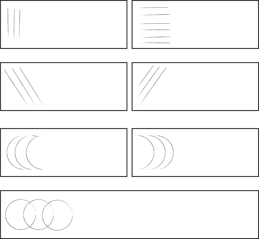
Next, try sketching the objects on this page. Make your sketches as much like the examples as possible.

Remember; sketching means freehand drawing. No Straightedges, compass, coins, etc!

2D objects to be drawn. The image displays two technical drawings on a white background. The top left corner shows a mechanical part design resembling a hook, with a prominent curved section and circular elements at both ends. Crosshairs are visible at these circles, indicating measurement points. Below this, another drawing depicts a more elongated mechanical component with three aligned circles, each intersected by crosshairs. These drawings are placed adjacent to two empty squares on the right side of the image.

Lettering

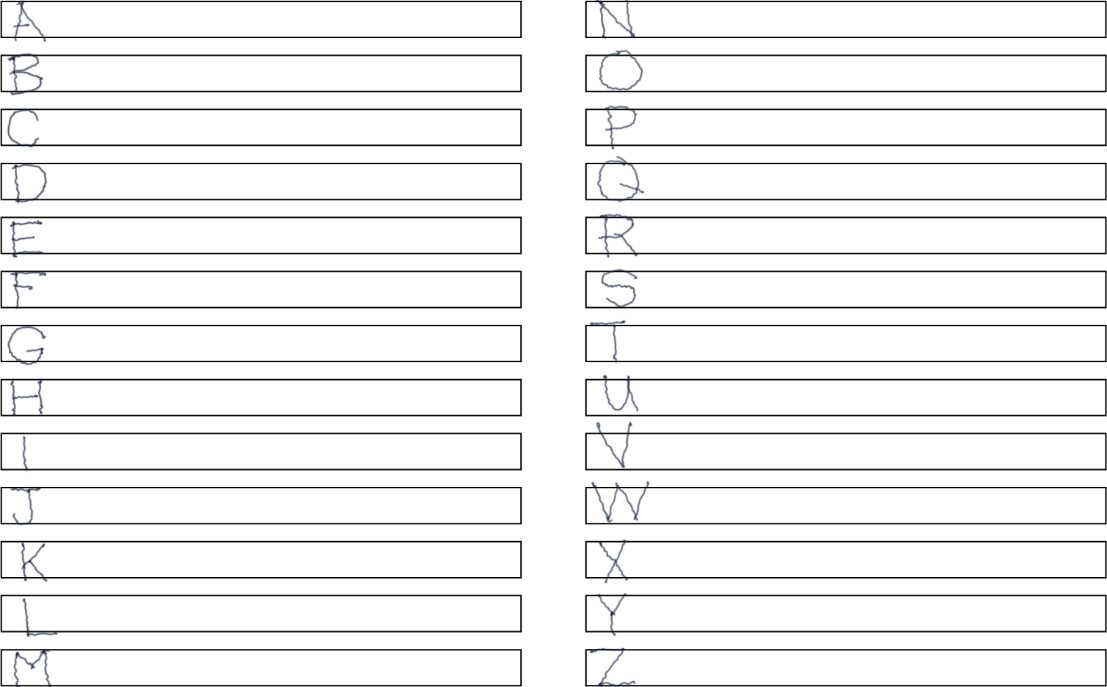
Now that you are warmed up, we will take the straight and curved lines from the sketching exercise and use them to form letters. The entire alphabet can be formed from the straight and curved lines you have practiced.

Look at the lettering below. If your printing is similar, and is easily readable, you can skip this exercise and go on to oblique sketching. If not, do some practicing. Some of the work ahead (and tests) require good lettering.

Remember, the most important requirement of good lettering is legibility. There is no use making a drawing if the person looking at drawing cannot read your writing.


Sample of hand written "ABCs". The image displays two columns of handwritten capital letters, each set against a lined background for practice. The left column includes letters A to M, and the right column displays letters N to Z. Each letter is positioned within a horizontal lined space resembling typical handwriting practice sheets. The letters are written in capital form with a basic, unembellished style, and the lines serve as guides to maintain uniform letter size and alignment.

Oblique Sketching

Oblique sketches are a type of pictorial having one plane parallel to the drawing surface, and the visible side sketched at an angle. Usually, that angle works best at 30 to 45, or somewhat in between. Beginners often have trouble keeping the 30 or 45 lines as the same angle. If that happens, your sketch will look distorted.

drawing 30, 60, 90 degree angles. The image depicts a diagram with three intersecting lines, forming angles with each other. The horizontal line is at the base, intersecting a vertical line that rises perpendicularly. To the right of the vertical line, another line extends at an angle, intersecting the vertical. Three angles are marked: 90 degrees between the horizontal and vertical lines, 30 degrees between the extension line and the vertical, and 40 degrees between the extension line and the horizontal.


Here’s how to sketch an oblique cube in three steps:

Making an oblique sketch from a 2D sketch. The image depicts a simple geometric diagram involving angles and lines. It features a horizontal line intersected by a vertical line, forming a right angle marked with a 90° arrow. Two additional lines extend from the intersection point on the horizontal line, slanting upwards to the right. These lines create two smaller angles with the horizontal line. The angle closer to the vertical line is labeled 30°, and the angle farther away is labeled 40°. Arrows are used to indicate the measurement of all angles.

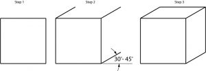
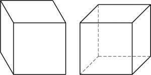
Possibly you might want to show the left side of the cube, or perhaps draw the hidden lines, as at the right;


Oblique cube with solid lines and cube with hidden lines. The image features two three-dimensional cubes. The cube on the left is a solid black outline with no visible interior lines, giving it a simple box appearance. The cube on the right also has a black outline, but it includes dashed lines to represent the edges that would be hidden if the cube were transparent, showing a more detailed perspective.


In the spaces below, sketch oblique cubes as indicated.

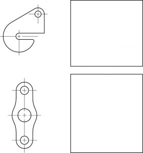
Sketch these objects in oblique, as shown:

Oblique objects to practice drawing. The image depicts four abstract 3D shapes on the left, each aligned horizontally with an adjacent blank rectangle on the right. The shapes are outlined and presented as follows from top to bottom: A shape resembling a staircase with two steps. A block with a concave curve on one side. A U-shaped block with two notches on top. A rectangular block with a slanted top on one side. Each shape is paired with a blank rectangular area that likely serves as a space for additional information or context related to each shape.

Book case, bench, scaffold, to be sketched. The image showcases three simple black and white line drawings of furniture on the left side, and three empty rectangular spaces on the right. The top left shows a rectangular bookshelf with three shelves inside, drawn in a perspective view. Below the bookshelf is a long bench with two supports underneath. At the bottom left, there is another bench depicted at a slight diagonal angle, supported by two intersecting pairs of legs forming an "A" shape.


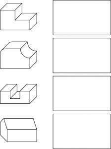
In this more difficult exercise, you are to make oblique sketches of the objects shown. The third problem is drawn in isometric. You are to sketch it in oblique. Convert problem four from orthographic to an oblique sketch.

Objects to be drawn. The image is a collection of geometric 3D shapes arranged in a grid-like layout. In the top left corner, there is a U-shaped object with a rectangular base. Directly below it is a rod-like structure with a circular end and an extended cylindrical arm. Adjacent to these, in the lower left section, is a complex shape resembling a triangular prism with additional rectangular facets. Below these, there are two more geometric blocks: a rectangular prism divided into smaller sections and a sloped rectangular block with a small cube next to it. On the right side of the image, there are four rectangular prisms of varying sizes, aligned vertically in descending order of size. They are simple and lacking any detailed features.

Isometric Sketching

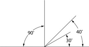
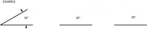
Isometric sketches, unlike oblique, must maintain an angle very close to 30°.

Therefore, to get the “feel” of an isometric, try sketching 30° angles in this exercise:


30 degree sketching exercise. The image displays three black line diagrams on a white background, illustrating angle measurements. On the left, there is an angled line intersecting a horizontal line, forming a 30-degree angle marked with a curve. The horizontal line is straight. In the middle and on the right, there are two identical horizontal lines, each labeled with the angle "30°" above them. These lines do not have intersecting lines or marked angles.


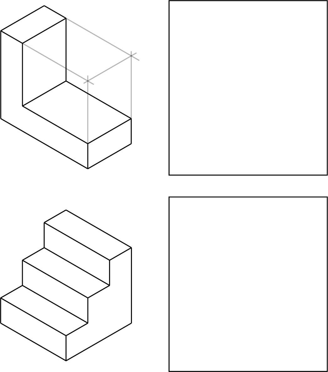
Sketching in isometric can be done in different ways. Generally, it’s recommended that you start and the bottom of the object and “box it in”, thereby enclosing it within a rectangular framework. For example, if we were to take a simple object like this,

90 degree angled object. The image depicts a simple black and white isometric drawing of an L-shaped object. The object consists of two rectangular prisms connected perpendicularly. One prism forms the vertical part of the L, extending upwards, while the other forms the base, lying flat. The edges are clearly defined with bold black lines, and the object appears hollow inside.

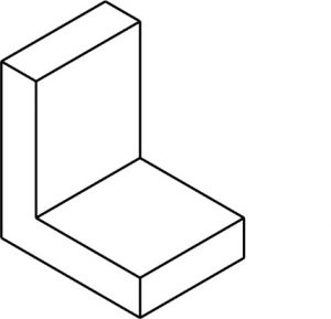
The steps needed to sketch it in isometric would be;


Steps needed to draw the 90 degree part. The image displays a sequence of three diagrams illustrating a cube's construction. On the left, Diagram 1 shows two lines intersecting at an angle, forming an upside-down "V" shape. In the center, Diagram 2 presents a complete cube drawn with solid lines, creating a three-dimensional effect. On the right, Diagram 3 depicts the same cube with one face removed to reveal its interior, emphasized by dashed lines for the missing edges. Each diagram is numbered above for reference.

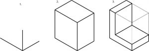
The unnecessary lines are then removed, leaving the object. Once you gain some practice at this, it will be possible for you to make an ISO drawing without the “guide” lines. It is important to use them early on the help train your brain.

To the beginner, building a “frame” before sketching the object often seems unnecessary. That may be true with simple objects. However, when things become more complex, a frame gives you a means of developing the various parts in an organized way. Without such guidelines you can easily “lose” your sketch.

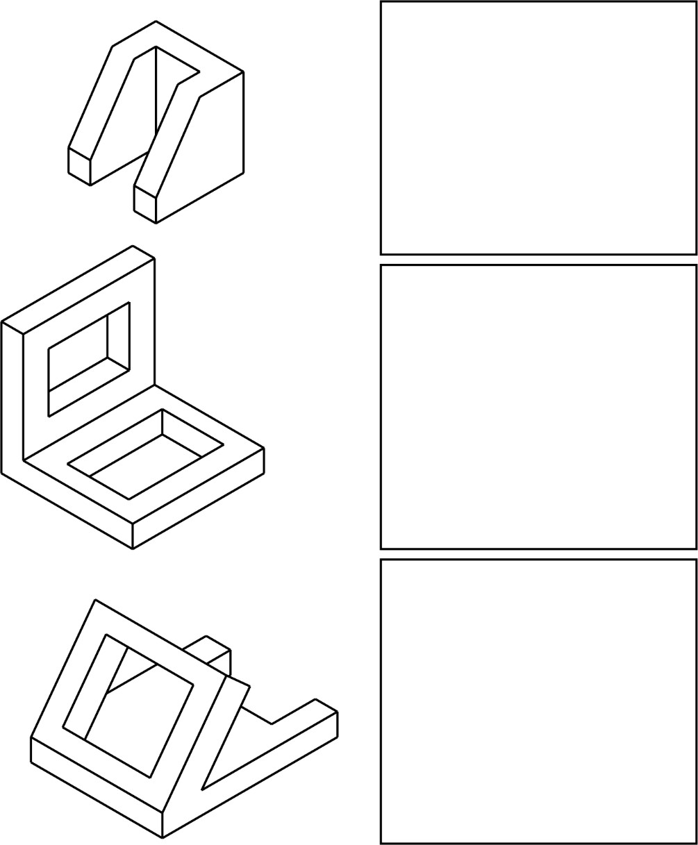
Sketch the examples given, using guidelines as shown in the first exercise. Draw the guidelines lightly. Notice that 3 and 5 require the use of non-isometric lines. Since those lines are not at 30, it is best to connect the end points of those lines after the sketch nears completion.


Isometric parts to sketch. The image consists of four sections, arranged in a 2x2 grid. The top left section displays an isometric drawing of an L-shaped object with three visible faces, one atop the other, giving it a three-dimensional appearance. Gray guidelines extend from the corners to indicate depth. The top right section is blank. The bottom left section shows a block structure composed of three ascending steps, drawn in an isometric view. The bottom right section is also blank. All elements are outlined with thin black lines on a white background.

Isometric objects to sketch. The image displays three isometric diagrams of geometric, angular 3D shapes on the left side, with three blank rectangles on the right. At the top left, there is a U-shaped object with a hollow center. Below it, a more complex shape includes an L-shaped framework surrounding a rectangular hole. The third shape is angular, resembling a combination of a square frame and a diagonal support. Each shape is outlined in black against a white background, with sharp, clean lines and no shading. On the right, there are three identical empty rectangles aligned vertically.


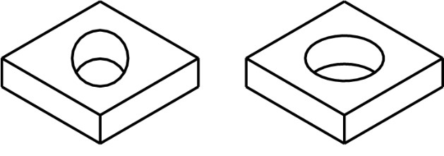
Circles and arcs, when sketched in isometric, become elliptical in shape. If a circle is used, it will appear distorted, as in this example:

The image consists of two identical geometric objects placed side by side. Each object is a three-dimensional square block with a circular hole through its center. The blocks are drawn using black outlines and are displayed at an isometric angle, giving a clear view of the top and two sides of each block. The left block's hole appears slightly slanted due to the perspective, while the right block's hole is shown with a consistent circular shape.

In sketching isometric circles and arcs, there are three positions in which they are normally sketched, depending upon the surface where the circular feature is located. Those surfaces, or picture planes are:

Circle locations on isometric cubes. The image displays three line-drawn cubes in a row: left, center, and right. Each cube is seen from a slightly different angle. On each cube, a circle is drawn on the front face, with two diagonal lines intersecting at the center. The circle on the left cube is on the vertical plane, the middle cube shows the circle on the horizontal plane, and the right cube has no visible markings. Below each cube, text labels them as "LEFT," "HORIZONTAL," and "RIGHT," respectively.


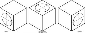
On the cube shapes below sketch ellipses as on the examples above.


Center marks on isometric cubes

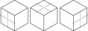
You may also want to practice sketching ellipses on the other surfaces of the cubes.

Isometric parts that need ellipses drawn. The image features a series of isometric drawings on the left side, illustrating objects with geometric shapes, and empty rectangles on the right side. The topmost drawing depicts a simple cylinder within a transparent cube, showcasing the cylindrical form and its enclosure in a three-dimensional space. Below this is a drawing of an L-shaped object, with a vertical rectangular piece and a cylindrical section on the horizontal base, also within a transparent cube. The lowest drawing presents a more complex L-shaped object, including two vertical pieces and an arched top connecting them, with a circular opening at the base. This object is also positioned within a transparent cube. On the right side, there are three empty rectangles aligned vertically, likely placeholders or frames for additional content.

Isometric parts to practice drawing ellipses The image displays three black and white line drawings of metal brackets alongside three blank rectangular boxes. The top left shows a wavy, elongated bracket with two holes at each end. Below it is a U-shaped bracket with two circular holes, one on the top and one on the bottom flat surface. The bottom left drawing is of an L-shaped bracket with a flat base and a vertical section with a hole at the top. The three blank rectangles are aligned vertically on the right side, corresponding with each bracket drawing.

Orthographic Sketching

Of all the methods of making drawings, orthographic projection is the most commonly used by draftsperson. Although the other methods serve their purposes, they cannot always show the parts of an object as well as orthographic representation.

Orthographic projection is a system of projecting from view to view to graphically describe the object. As a way of reviewing, study the views of the small garage in this drawing. Notice the location and relationship of each view to the other views.

Orthographic projection drawing of a house. The image displays an orthographic projection of a simple house structure. It is divided into three main views: top, front, and side. The top view presents a rectangular shape divided into three sections, likely representing the roof and two symmetrical sides. The front view shows a triangular roof atop a rectangular base with a rectangular door centered. The side view is a rectangle with a smaller rectangle inside, representing a window. In the upper right corner, there's a small 3D isometric sketch of the house, illustrating its overall shape with two visible sides and a pitched roof.

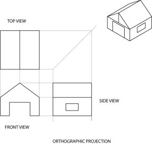
The important thing to remember in orthographic sketching is the alignment of views. The top view is projected directly above the front view. The front and side view also line up with each other. The height, width, and length of the object must remain the same from view to view. There should be enough distance between the views to prevent crowding; and to leave room for dimensions.

Produce a top view in the drawing below.

Isometric part for orthographic drawing. The image contains a 3D isometric drawing and two 2D orthographic projections of an object. The object is represented as a rectangular block with a slanted top surface and a circular hole through it. The 3D drawing is located in the upper left corner, showing the object with the hole visible on the top surface. Below this, the two 2D drawings depict different views. The left drawing displays a right-angled triangle shape, indicating the sloped side, with dashed lines suggesting hidden features. The right drawing shows a rectangle representing the front view, with dashed lines marking the circular hole's position within the object.


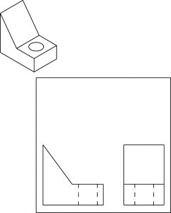
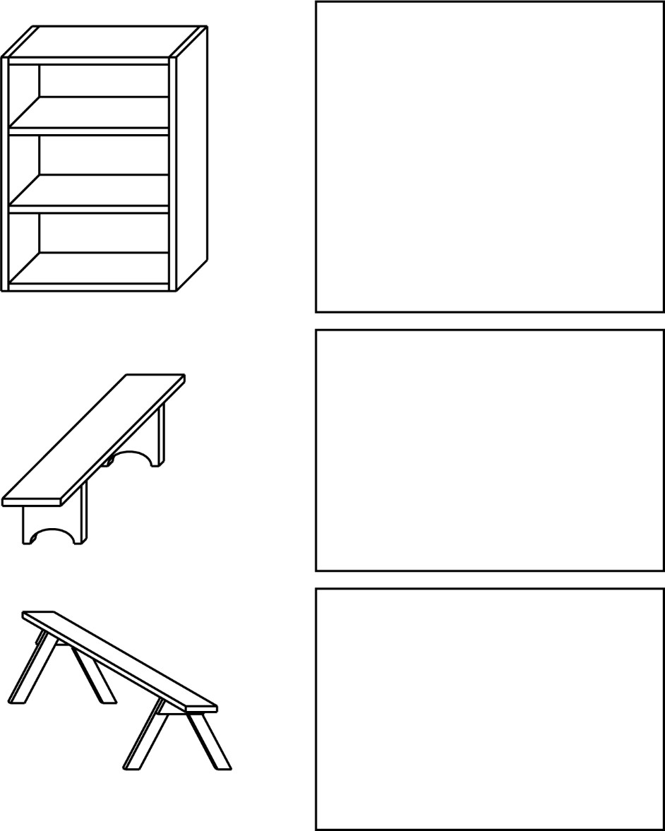
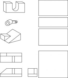
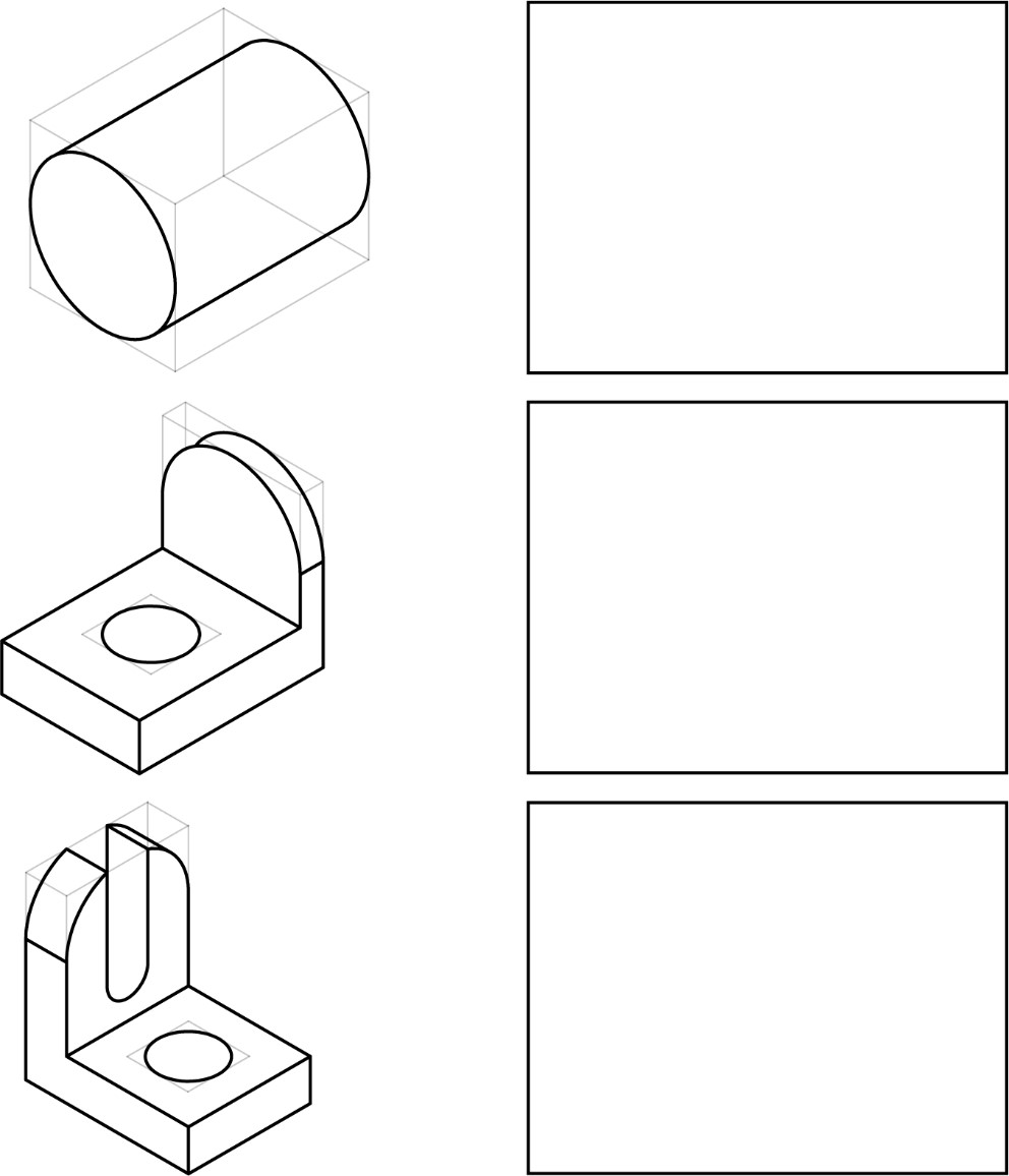
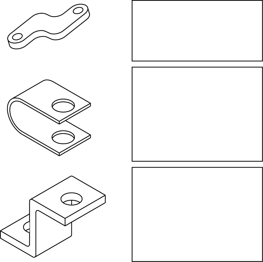
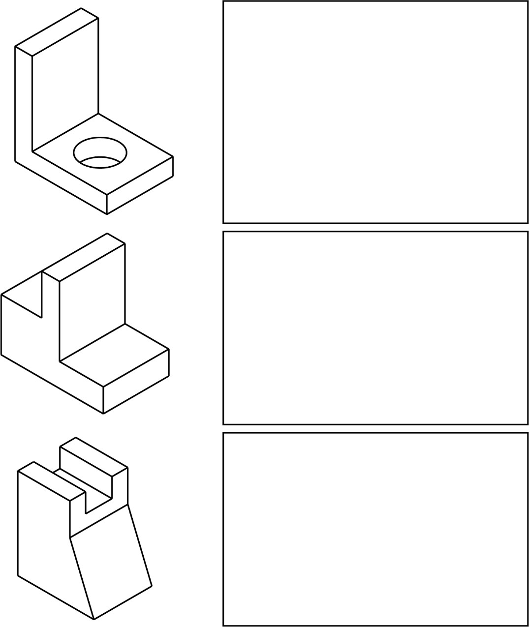
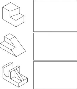
Sketch each object in orthographic in the spaces on the right. Remember, the idea is to project! Front, top and right side view.


Isometric parts to sketch orthographic views. The image features three isometric illustrations of different geometric objects on the left and three rectangular blank spaces on the right. The top-left object is an L-shaped bracket with a circular hole on the horizontal surface. Below it, the middle object is a stepped L-shaped block with a thicker vertical tab. The bottom-left object is a tapered shape with two vertical notches on the top edge. Each object is outlined with black lines and shown against a plain white background. The rectangular spaces on the right are evenly spaced and empty.

Isometric parts to practice drawing orthographic projections. The image features three geometric isometric drawings on the left side with corresponding empty rectangular spaces on the right. The top left drawing is a stepped structure with three distinct levels, resembling a simplified staircase. Below it, the second drawing is a longer, slanted structure with three steps on one side and a sloped surface on the other. The bottom left drawing shows a more complex 3D shape with a U-shaped cutout and angular elements, featuring a vertical support bar and a slanted surface. The right side of the image contains three empty rectangles, each aligned horizontally with the respective isometric drawings on the left.

“On-THE-SPOT” Sketching

Now that you have learned the three different methods of sketching, it is time to make sketches you can place in front of you and touch, rather that sketching from drawings on paper.

Sketching “ON-THE-SPOT” is a standard industry practice. A piece of machinery needs to be changed, a support needs to be added, or pictorial information in some way requires a sketch.

Instructor will give you an object to sketch…

You will need to produce an isometric of the object and also an orthographic drawing with as many views as required to show details of object to be built.

License

Icon for the Creative Commons Attribution-NonCommercial-ShareAlike 4.0 International License

Blueprint Reading For CAD I Copyright © by SBCCOE is licensed under a Creative Commons Attribution-NonCommercial-ShareAlike 4.0 International License, except where otherwise noted.

Share This Book