7 Auxiliary Views
- FRONT VIEW AUXILIARIES
- TOP VIEW AUXILIARIES
- SIDE VIEW AUXILIARIES
- SKETCHING AUXILIARY VIEWS
When an object has a slanted or inclined surface, it usually is not possible to show the inclined surface in an orthographic drawing without distortion. To present a more accurate description of any inclined surface, an additional view, known as an auxiliary view, is usually required.
An auxiliary view is simply a “helper” view, which shows the slanted part of the object as it actually is. It turns, or projects, the. object so that the true size and shape of the surf ace (or surfaces) are seen as they actually are.
Auxiliary views are commonly found on many types of industrial drawings.
Front View Auxiliaries
There are three basic type of auxiliary views. In the first type, the auxiliary view is projected from the front view of a three view (orthographic) drawing. In the second and third types of drawings, the auxiliary views are projected from the top and side views.
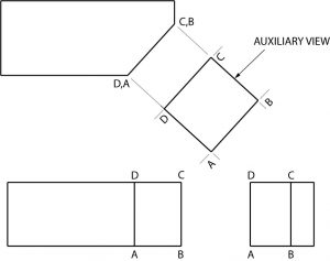
Here is a front view auxiliary of a simple object with an inclined surface.
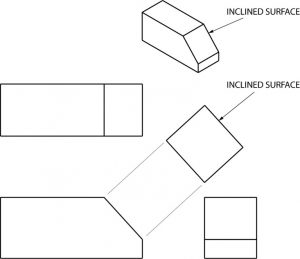
Notice that the projection lines are perpendicular to the slanted surface of the first view, and that only the slanted surface of the object is shown in the auxiliary view. · The rest of the object is omitted, however, for clarification portions of the adjacent· surfaces are sometimes shown. Also, notice that the slanted surfaces of the top and side views are shortened because of distortion, whereas the surface of the auxiliary view is true, or actual size.
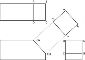
To sketch an auxiliary view, you begin with orthographic. views of the object and add projection lines perpendicular (90◦) to the slanted surface, adding a reference line any convenient distance from the view with the slanted surface.
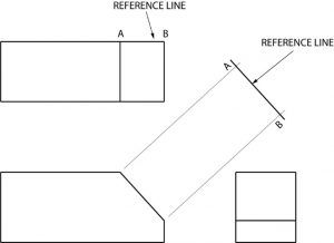
Next, the distance CB on the auxiliary view is made the same length as the related distance in one of the orthographic views; in this example it’s the side view. This completes the auxiliary view.
Top View Auxiliaries
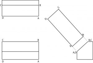
A top view auxiliary is developed in the same way as a front view auxiliary, except that the auxiliary is projected from the top view.
Whether the auxiliary view is to be projected from the front, top, or side view depends on the position of the object, or which surface of the object is slanted. In this example, the top view is slanted. Therefore the auxiliary view must be projected from the top view.
Again, notice how the angled surfaces shown in the front and side views are not shown in true length.
Side View Auxiliary
Side view auxiliaries are drawn in the same way as front and top view auxiliaries. Again, where the auxiliary view is to be projected depends upon the position of the object or which surface of the object is slanted.
Obviously, these are very basic auxiliary view examples and are presented to introduce you to the concept of auxiliary views.
As objects with inclined surfaces become more complex, auxiliary views provide a means of presenting objects in their true size and shape.
Sketching Auxiliary Views
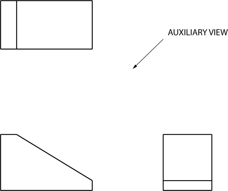
The following problems require and auxiliary view to be complete. Sketch the auxiliary views required in the spaces provided.
Drawing practice 1
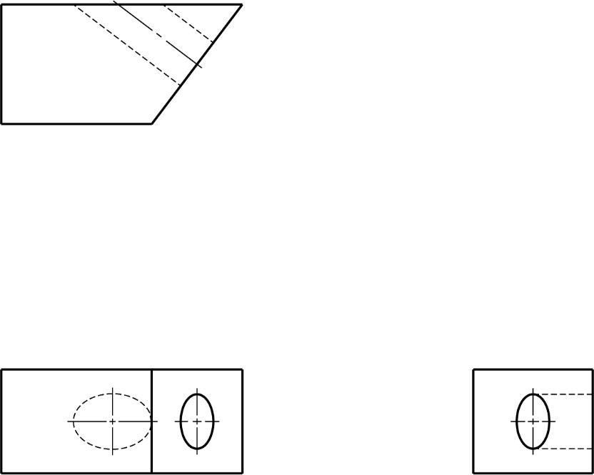
Drawing practice 2
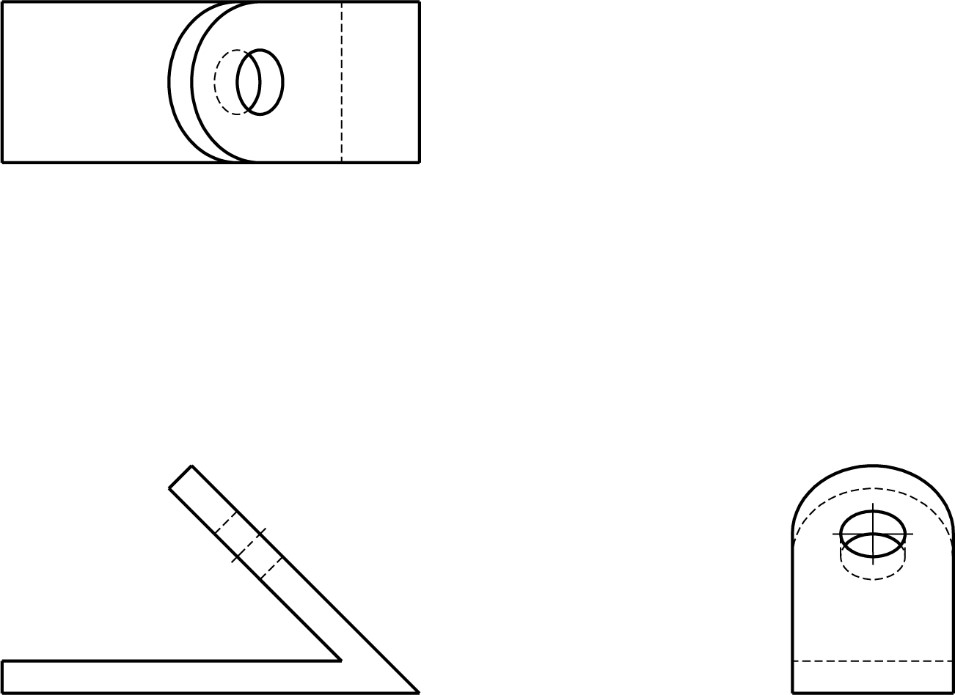
In this problem, a round hole is centered on the slanted surface and drilled through the object. The hole appears elliptical in the. front and side views because of distortion. It will appear in its true shape on the auxiliary view. Remember that the auxiliary is developed from the view with the slanted surface. Complete the auxiliary view.
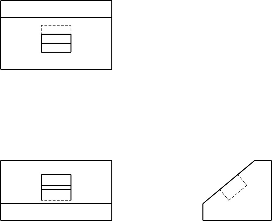
Drawing practice 3
In this problem, a square hole has been cut part way into the object. Complete the auxiliary view.
Quiz
Directions: Complete the auxiliary view in the space provided.